Thursday, June 23, 2011


Poster Text
PROPOSAL:
The Bennelong Wave is a proposed development to replace the current Bennelong Apartment complex of Circular Quay. Designed to complement the neighbouring Sydney Opera House with its white finish, arches and glass facade, the Wave’s organic undulating form has also been designed to connect with, and bridge the gap between, the two distinct modes of landscape it is
bounded by. The Wave is a study of the way in which architecture can connect both physically and symbolically with the landscape around it. From the water, the undulating curves of the roof provide a metaphorical link to the waves of the harbour, while the partially grassed roof, gradually sloping upwards from ground level at its rear to its highest point at the water’s edge, connects with the parkland of the Botanical Gardens by providing a physical extension of the landscape.The Wave is also an exploration of contemporary energy efficiency, with a relatively low, squat shape designed to increase the surface area exposed to sunlight at any given time, and allowing maximum efficiency from the solar panels and skylights installed on the roof.
USAGE:
The Bennelong Wave will be a mixed residential, retail and recreational complex. Retail shops and restaurants will occupy the lower levels, with some of these retail outlets fronting on to the pedestrian walkway, and the others forming a large shopping centre further inside. The upper levels will consist mainly of residential units, the majority of which will enjoy stunning harbourside views. It is envisaged that the gently sloping roof will capitilise on its physical connection to the Botanical Gardens by being open to the public, allowing sightseers the opportunity to experience fantastic views from the very top, as illustrated in the image to the right.
ORIGINS:
The Wave was inspired by a study into the ways in which surface architecture can be used to create links to the landscape, as well as to promote environmental sustainability. The works of Toyo Ito were of particular significance in regards to this. His use of complex geometry to mimic aspects of nature, as well as his attempts to blend his architecture with the landscape by physically submerging parts of his buildings, directly correlates to what the Wave attempts to achieve. An example of this is the Yatsushiro Municipal Museum, which features an elegantly
curved roof symbolic of a bird in flight, while an entire section of the building is sunken into the earth, its roof transformed into a hilly landscape. The architecture firm B.I.G. Architects was
another source of inspiration, with their dynamic explorations of the boundaries between built and natural elements through the grassing of large sections of their designs.
ITERATIONS:
The iterations presented here explore variations both in form and surface structure. The seven iterations on the left are alternatives to the rooftop curves seen in the montages above. These variations were produced through altering the frequency and amplitude of sine curves within
Grasshopper, and it is interesting to note the potential impact these alternative forms could have on the way in which the building links to the harbour. The five iterations on the right explore different representations of materiality and surface structure on the roof of the Wave, and the potential ramifications of this both on the aesthetic qualities of the building and on its energy efficiency. For example, the merits of long open strips across the roof for lighting and ventilation purposes versus a more enclosed, tighter configuration.
Final Poster
My poster file is too big to upload, even as a JPEG, so I have uploaded it to www.megaupload.com.
Here is the download link:
http://www.megaupload.com/?d=M830V7I4
I've included a screenshot of the poster just to give you an idea:

Here is the download link:
http://www.megaupload.com/?d=M830V7I4
I've included a screenshot of the poster just to give you an idea:

Final Physical Model
Here is my final physical model. I managed to cover up most of the burn damage by spray painting the entire model white, although the surface is still bumpy in some areas where sand paper was ineffective. I grassed two distinct channels up the areas of the roof that have the least slope, and these are the areas I envisage the public having access to.


Flat Cut Material
Here are some images of my material as I received it from the Design Lab (some of the pieces have already been removed). I ended up using 9mm MDF, 2mm perspex and 1.6mm box board.
Unfortunately, what I discovered on attempts to remove the MDF pieces from the main sheet was that due to the material's thickness, quite a few of the pieces hadn't cut all the way through. It took me hours to cut some of the pieces out with a scalpel, and the process resulted in some slightly rough edges and some small cracks where the wood split as I was trying to lever the pieces out. On top of this, because the laser was cutting for so long to slice through the MDF, the sides of each piece are very burnt, and will need to be sanded down to remove any charred layers. I am hoping these issues do not affect the look of my finished model too much.


Unfortunately, what I discovered on attempts to remove the MDF pieces from the main sheet was that due to the material's thickness, quite a few of the pieces hadn't cut all the way through. It took me hours to cut some of the pieces out with a scalpel, and the process resulted in some slightly rough edges and some small cracks where the wood split as I was trying to lever the pieces out. On top of this, because the laser was cutting for so long to slice through the MDF, the sides of each piece are very burnt, and will need to be sanded down to remove any charred layers. I am hoping these issues do not affect the look of my finished model too much.


Montages of Final Model
Here are a few montages showing the model in context, as well as one portraying a view from the roof.


Laser Cutting Files


The above images show my laser cutting files both within Grasshopper and as they were submitted to the Design Lab. There ended up being 39 cross sections, 10 columns and 1 facade, spread over four sheets.
Thoughts on Laser Cutting
I have decided that the easiest way to fabricate my model will be through taking multiple thin cross sectional slices and then sticking them together to build up a form that mimics the slope and undulation of my concept.
The material I use will need to be quite thick to avoid having to generate literally hundreds of cross sections, so 10mm MDF is probably the way to go. Even at that thickness, in order to come out with a model of decent size, I'll need up to 40 cross sections (assuming I want to use all of the 40x40cm space provided to us for the exhibition).
As for the glass facade, 2mm or so perspex would be ideal, possibly frosted if I can get my hands on it. The columns running down the face of the glass could probably be cut from plain box board, as I will need something fairly lightweight to attach to the perspex facade.
To further resolve my model, I will most likely glue some model grass or shrubs to the roof of the structure, to represent my key concept of extending the parklands to the rear of the building.
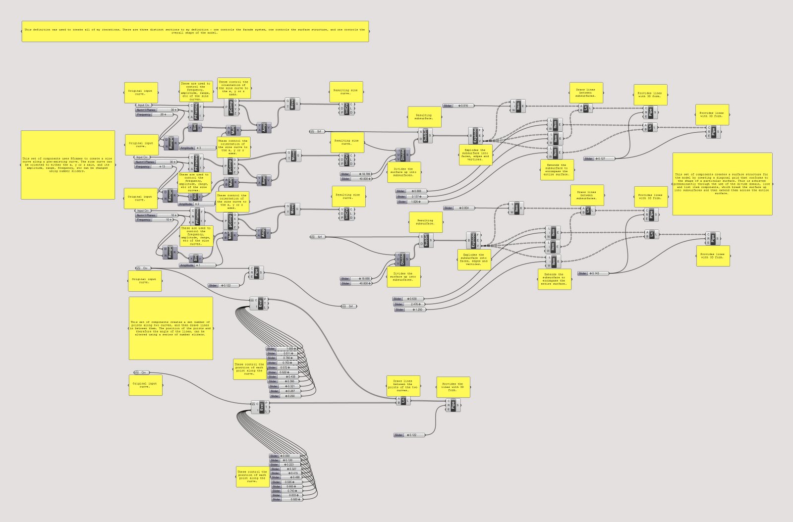
Preliminary Final Definition
Below is my description file with all components included. There are three distinct sections to the file - the components related to the creation of the facade system, the components responsible for the generation of different surface structure, and the components responsible for the overall shape of the model. Together, they are able to produce unique and interesting forms. Two such forms can be seen below - the top one is the model used for laser cutting, and the second one is one of the new shapes I was able to generate by altering the sine curves within my definition.


Further Progess


 While my basic system worked on one level (in terms of surface structure), I needed to include a means to alter the overall shape of my model at any given time. This led to an overhaul of the way I had approached the creation of my system up to this point. The definition above uses Pframes to create a sine curve along any given curve, with sliders altering the frequency, amplitude, range, etc. By building this into my overall definition, I was able to alter the undulations of my model at different points along its length. As you can see in the top image, I ended up applying this definition to three points along the length of my building. For each iteration, I used sliders to alter the form of each curve and then lofted a surface between them, generating a new shape for my model.
Assignment 3 Progress


Working off my original model, the facade has been added to the structure using lines stretched between points set along two curves. The lines were then piped to give them 3D form.
Thursday, June 2, 2011
Grasshopper Experimentation
I have developed a rough, basic system which outlines the basic shape I am proposing for my design. Bear in mind this does not include the glass facade, nor does it include any details such as the grassed area or solar panels.
The system uses the divide domain, line and list item components to generate a diagonal grid of subsurfaces across any given surface. Sliders can be used to alter the number of divisions, the orientation of the lines, and the width of the lines. In this way I am able to explore materiality and surface structure within my model.


The system uses the divide domain, line and list item components to generate a diagonal grid of subsurfaces across any given surface. Sliders can be used to alter the number of divisions, the orientation of the lines, and the width of the lines. In this way I am able to explore materiality and surface structure within my model.


Subscribe to:
Posts (Atom)